Conception
33 TONS: manufacturing of an exceptional SPEED reducer for a circular rolling mill
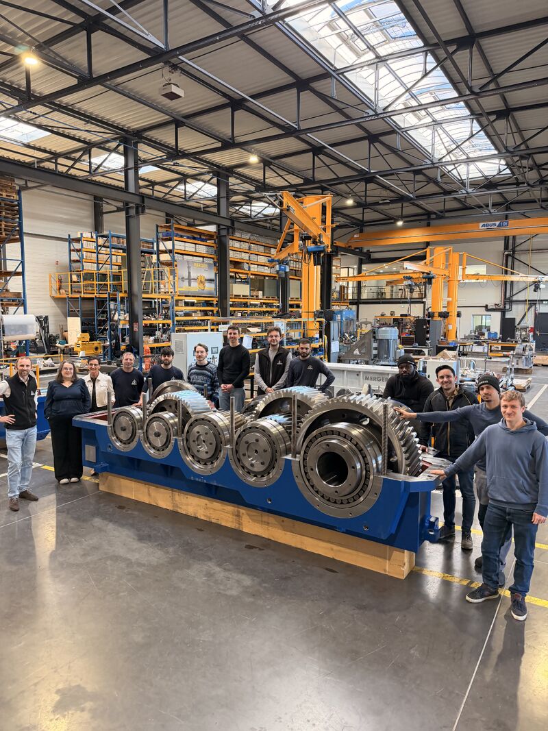
Intended for a steel industry player based in Italy, MERGER manufactured the power transmission components of a circular rolling mill including a main reducer of 33 tonnes and two cone reducers of 10 tonnes each.
100% MERGER design for an Italian steel industry player
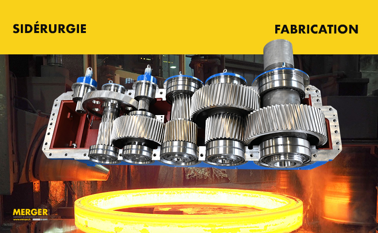
MERGER designed, assembled and tested in its Corbas workshop a mechanical transmission system with a total mass of 53 tonnes . This equipment, comprising two 10-tonne cone reducers and a 33-tonne main reducer, is intended for the modernization of a radial-axial circular rolling mill operated by a steel company based in Italy.
Restructuring the drive train of a rolling mill: the client's industrial challenges
The steelmaker has undertaken the restructuring of its powertrain to meet three main objectives:
- Evolving the infrastructure for allow hot rolling of steel crowns diameters higher, an operation requiring a significant increase in the applied torque.
- Limit the diversity of rooms spare parts stored on site by imposing a single type of motorization for the entire process (exclusive use of ABB M3BP 400 type electric motors, each developing 630 kW).
- Eliminate the risk of unplanned downtimeIn steelmaking, a transmission failure in a hot flow leads to the cooling of metal blanks, raw material losses, and increased costs. Compliance had to be 100% factory validated before shipment as part of immediate commissioning.
A technical challenge: the specific features of MERGER gearboxes
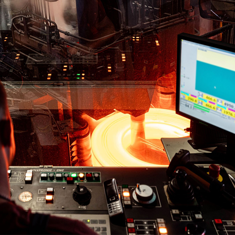
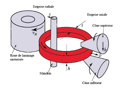
The rolling mill initially receives a thick, small-diameter, circular blank of raw steel. This solid piece is heated to a high temperature to make it malleable. The main roller then exerts continuous pressure on the wall of this rotating ring. Under the effect of this mechanical force, the steel is crushed, stretched, and thinned. The material expands outwards. This mechanical rolling thus increases the final diameter of the ring while reducing its thickness, in the same way that a ring of dough is enlarged by rolling it. To withstand the mechanical stresses induced by the application, our teams had to install axial load-bearing stops. Particular attention was paid to their sizing.
Location and function of the 33-tonne main reducer
The main reducer provides the drive for the central rolling mill. Its function is to transmit the power required to deform and stretch a hot steel ring.
This power is obtained by coupling 2 ABB M3BP 400 type motors, each developing 630 kW. Operating simultaneously, the total power at the input of the gearbox is 1230 kW.
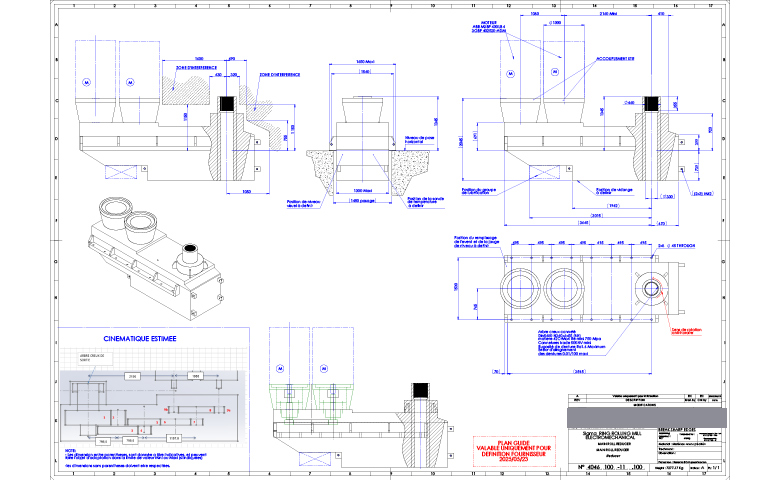
Kinematics and dimensioning of the main gearbox
Cinematics:
-
Architecture: Dual-Input / Single-Output parallel input-tree system.
-
Reduction stages: 4-gear train configuration.
-
Power flow: The two high-speed input gears receive power from both motors. They mesh with a common intermediate gear set to combine the torques. They then transfer this total power to the low-speed shaft .
-
Direction of rotation: Counterclockwise.
sizing
-
Exact reduction ratio: 80,248.
-
Rated power accepted: 2 x 630 kW (i.e. a total installed power of 1,260 kW).
-
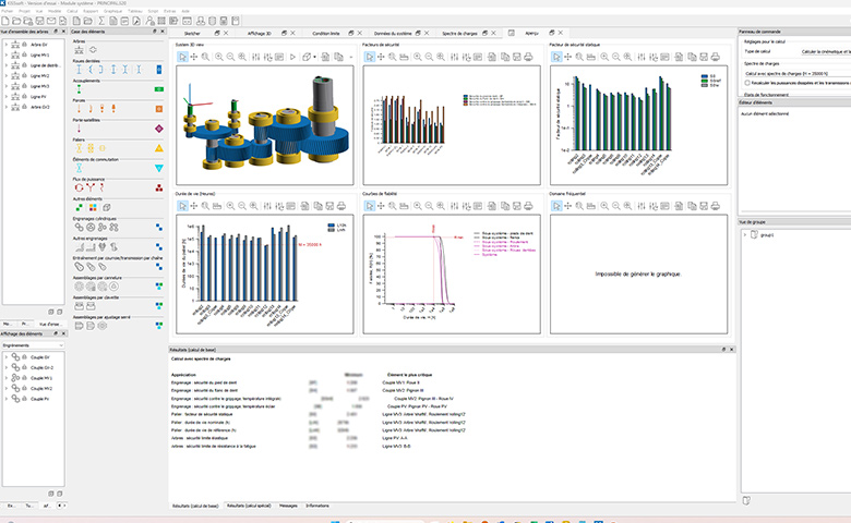
Strength calculations: The MERGER design office carried out the calculations of the geometry and tooth profiles using KISSsoft software according to the ISO 6336 standard. A complementary study with CETIM validated the resistance of the shaft lines to thermomechanical stresses.
Mechanical characteristics and weight
Mechanical characteristics:
-
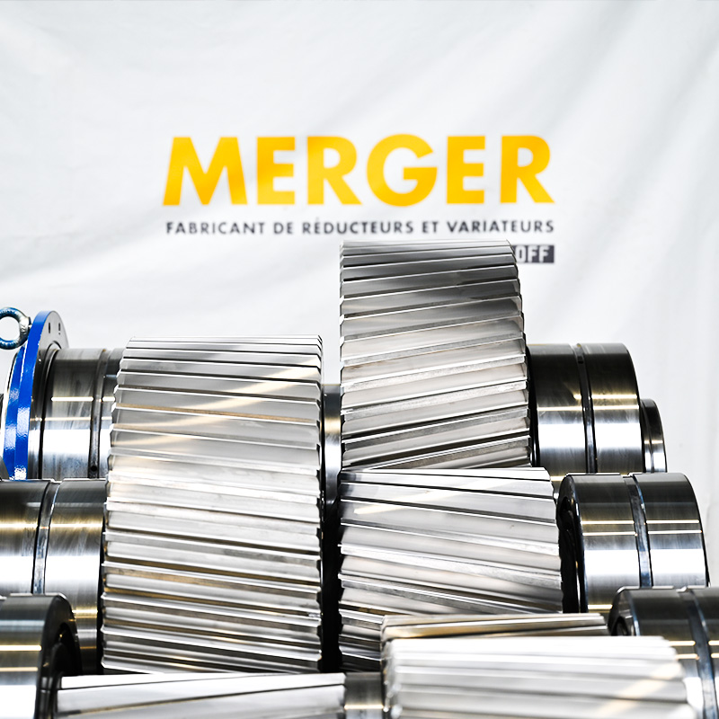
Gear material: 18CrNiMo7-6 steel. In metallurgical classification, this grade is by definition a special steel for case hardening. Its low carbon content (~0,18%) necessitates a surface carbon application (case hardening) followed by heat treatment (quenching) and a stabilizing tempering process to achieve the desired hardness/hardening ratio. These operations are commonly referred to as CTR (case hardening/quenching/tempering). These heat treatments are carried out after the gears are cut, but before the final grinding stage.
-
Connection and output interface: Hollow splined shaft according to DIN 5480 (N340 x 6 x 55 – 8H) . This shaft uses treated 42CrMo4 steel ( Re > 750 MPa ) with induction-hardened splines at a minimum of 500 HV.
-
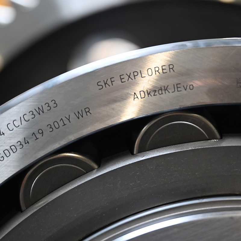
Guidance (Bearings): The shaft lines rely on high-capacity SKF bearings . They incorporate a C3 radial clearance to absorb thermal expansion in steelmaking.
-
Lubrication and sealing: The system combines splash lubrication with forced lubrication from an external pump unit with a duplex filter. O-rings on the covers and labyrinth seals at the shaft outlet ensure sealing.
Weight:
-
Empty mass: Approximately 8,500 kg (27 tonnes).
-
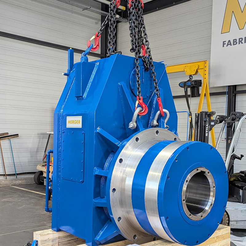
Weight in working order: 33,000 kg (33 tonnes). This weight includes a full tank of lubricant, couplings, and accessories. This is the heaviest transmission built by MERGER in its workshop in Corbas (69).
The 10-tonne cone reducers
These two units (upper and lower cones) manage power transmission on the secondary and complementary geometric axes of the radial-axial process. They drive the cones that pinch and calibrate the steel on its end faces. They thus control the height of the ring while the main gearbox increases its diameter.
These gearboxes are positioned immediately around the forming area . They are inclined at 17,50° to the floor level of the rolling mill . One drives the upper drive and the other drives the lower drive. The two units rotate in opposite directions.
Kinematics and dimensioning of cone reducers
Cinematics:
-
Architecture: Orthogonal combined reducer.
-
Reduction stages: 3-gear train configuration.
-
Power flow: The first input stage uses a spiral torque to change the direction of the motor input shaft by 90°. Then, two parallel helical gear trains perform the main speed reduction.
-
Direction of rotation: Clockwise and counter-clockwise.
Dimensioning:
-
Exact reduction ratio: 19,104.
-
Rated power accepted: 630 kW per unit.
-
Rated speeds: The device reduces the speed from 1,491 rpm input (ABB M3BP 400 motor) to 78 rpm output.
-
Durability calculations: The modeling under KISSsoft guarantees the behavior of the teeth in the face of cycle reversals and penetration shocks on the steel billet.
Mechanical characteristics and weight of the 2 reducers
Mechanical characteristics:
-
Gear material: As with the main reducer , the material for the helical and spiral bevel gears is case-hardened, tempered and ground alloy steel (CTR).
-
Connection and output interface: Rigid hollow shaft coupled with a shrink disc ( bore , ). This system ensures a keyless friction connection . It eliminates mechanical play and is not subject to vibration or load reversal.
-
Guidance (Bearings): The hollow shaft uses SKF tapered roller thrust bearings , which take the axial thrust of the cone , and large spherical roller bearings (500 x 830 x 325) take the radial forces.
-
Lubrication and sealing: A network of internal rigid pipes and injection manifolds spray pressurized oil directly to the points of engagement. Labyrinth seals protect the bearing housings from descaling water, scale, and other surrounding contaminants.
Weight:
-
Empty mass: Approximately 8,500 kg (8,5 tonnes).
-
Mass in running order: 10,000 kg (10 tonnes) per unit. This weight includes the lubrication system, fluids, engine interface bracket and accessories (sensors, valve, etc.).
Photo gallery
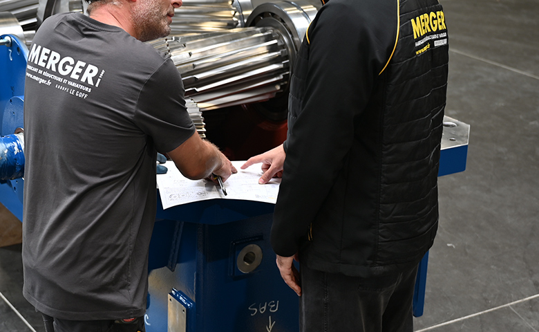
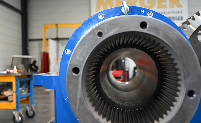
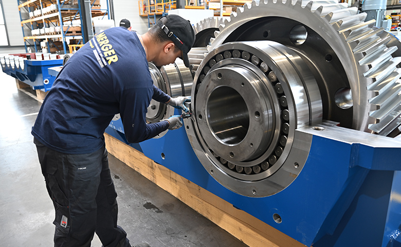
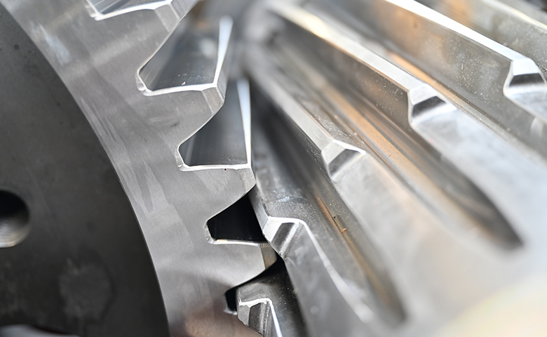
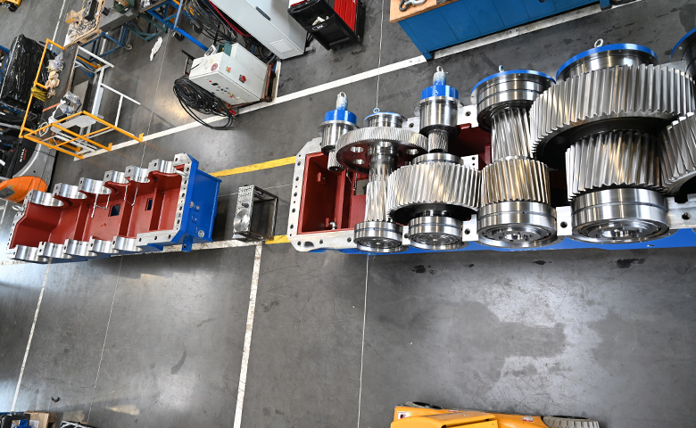
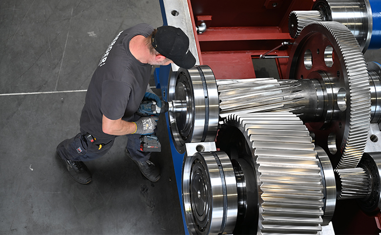
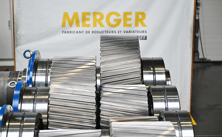
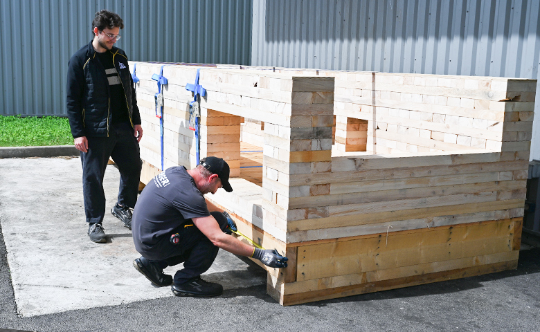
Hot rolling: the principle of mechanical deformation
The machine initially receives a rough piece of steel (called a blank or rough ring), which is thick, tall, and has a small diameter. This massive piece is preheated to a very high temperature to make it malleable.
The rolling mill then uses the combined force of several cylinders to crush and stretch the metal:
- Radial action (controlled by the main reducer): The main cylinder exerts continuous pressure on the outer wall of the rotating ring. Under this extreme mechanical force, the steel is crushed, thinned, and stretched. This action increases the final diameter of the crown.It's the same physical principle as when you widen a ring of dough by rolling it between your fingers: the thinner the wall becomes, the larger the diameter of the ring gets.
- The axial action (managed by the cone reducers): As the diameter increases, two conical cylinders clamp the steel on its upper and lower faces. This action allows to precisely calibrate the height and flatness of the crownpreventing the metal from deforming uncontrollably under the pressure of the main cylinder.
For which finished product?
Thanks to this simultaneous double work (radial and axial), the rolling mill transforms a compact block of metal into a large diameter steel crown or ring , perfectly circular, with strictly controlled thickness and height.
These parts (seamless rolled crowns) are then used in high-tech industries to manufacture:
-
Very large bearings (for wind turbines or tunnels).
-
Connection flanges for tanks or pipelines.
-
Components for the aeronautics, rail or space sectors.
The technical constraints of this manufacturing process
Constraints related to the final application:
The hot rolling process for crowns creates a demanding working environment, particularly for transmission components:
-
Combined multidirectional forces: The process simultaneously applies loads on two distinct geometric axes. The gearboxes must absorb continuous radial forces during the ring thickness reduction, as well as permanent axial forces during the calibration of the end faces.
-
A regime of repeated mechanical shocks: The engagement of the thermal steel blank between the rolling cylinders causes instantaneous load peaks (penetration shocks) which are directly transmitted to the shaft lines and gears.
- Difficult thermal conditions and pollution: The housings operate in the immediate vicinity of the metal in MERGER. They are subjected to strong thermal radiation, water spray related to the descaling process and an atmosphere saturated with scale, a highly abrasive iron oxide particle.
The architectural requirements of the specifications
The steelworks operator has formulated specific criteria with a view to standardizing its plant:
-
A unique motorization constraint: The customer is restricted to the exclusive use of standardized ABB 630 kW electric motors.
-
A mandatory twin-motor architecture: To achieve the required power of 1,260 kW on the main drive with these imposed motors, MERGER had to design a specific gearbox with a parallel double input shaft incorporating a mechanical power summation system.
-
Precise reduction ratios: The devices had to comply with strict kinematics, namely an exact ratio of 80,248 for the main reducer (4 reduction trains) and 19,104 for the cone reducers (3 stages with 90° angle drive).
- Zero defects before shipment: Because of the critical financial costs that a failure on a hot metal flow would entail, MERGER had to 100% validate the performance and durability of the gears on its factory test bench (vibrational, thermographic analyses and blue contact tests) before the delivery agreement.
The specific solutions proposed by our design office
To precisely meet the constraints of the Italian rolling mill, MERGER's design office studied all the constraints related to the specifications and proposed specific solutions validated by the client.
- The implementation of a forced lubrication system: To dissipate the heat generated by the process and internal operation, each reducer is associated with an independent motorized lubrication unit, equipped with flow sensors, filters and oil cooling blocks.
- A reinforced sealing system: To protect the internal mechanics from process water and scale, MERGER has implemented specific dynamic sealing systems (labyrinth seals and baffles) at the shaft outputs. The shaft outputs are thus protected by non-contact systems, preventing any contaminant from entering the bearings.
- The choice of reinforced SKF bearings: The guidance is provided by high-capacity roller bearings from the catalog SKF (specifically the 22344, 22356, and 23264 series for the main gearbox). They were specifically selected with a C3 radial set in order to absorb significant temperature increases without risk of blockage or seizing of the balls/rollers.
Our service: from the initial study to the delivery of rolling mill gearboxes
The engineering phase, calculation notes and modeling
The project begins with an essential study phase to size equipment subjected to extreme torques and repeated shocks.
Gear strength calculations: MERGER's internal design office used KISSsoft simulation software to model the gear profiles and calculate their fatigue and breakage resistance according to the international standard ISO 6336. MERGER provided a calculation note for the entire project.
Co-validation of shock resistance: MERGER collaborated with expert engineers from CETIM (Technical Center for Mechanical Industries) to validate the mechanical resistance of the shaft lines and the absence of deformation of the housings with respect to load peaks during the penetration of the steel into the rolling mill.
Design of specific architectures: Our engineers drew up the overall plans for the twin-motor housing with parallel axes (main reducer) and the orthogonal housings (cone reducers).
Manufacturing, cutting and thermochemical treatments
-
Machining and cutting of the gears : All the gears were machined from a solid block of steel specific to the metallurgy/steel industry.
-
Heat hardening treatments : The gears underwent a carburizing-quenching cycle.
-
Final profile grinding : After processing, the gear teeth are ground on high-precision machines to achieve perfect geometry and very low maximum roughness ( Ra = 0,8 ). This operation is particularly important for achieving smooth meshing, limiting heat generation, and reducing vibrations.
Mechanical assembly and adjustment in the workshop
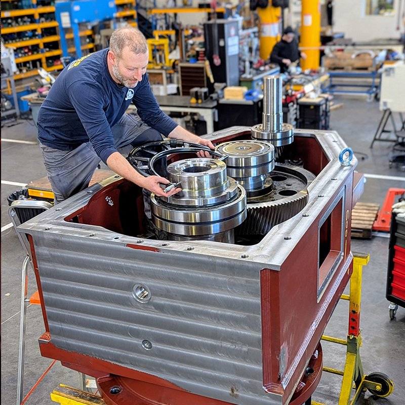
The assembly took place in our workshop in Corbas. One month was required from preparation to delivery for the main gearbox.
-
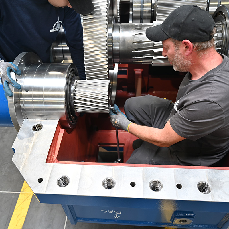
Bearing assembly: SKF bearings are installed using a heat-fit system. Tapered roller bearings are used for the cone input shaft, and spherical roller bearings are used for the main gearbox. The main gearbox bearings have a specific adjustment adapted to the thermal constraints of the steel industry.
-
Tooth contact test using Prussian blue: Before closing the housings, a mechanical contact test using Prussian blue is performed. This allows visual verification that the contact surface between the teeth is perfectly distributed across the entire width of the pinion.
-
Casing adjustment and closure: The welded steel casings are assembled. The structural screws, of quality class 12.9 , are tightened to the nominal torque using controlled torque tools. All internal keys used undergo a treatment giving them a minimum hardness of 110 daN/mm².
Analysis and control
Before delivery authorization, each unit underwent a control protocol under no-load and load conditions to validate dynamic behavior.
-
Spectral analysis of vibrations: Accelerometers measured the vibrational behavior of the gears and bearings to detect the slightest meshing anomaly.
-
Thermographic monitoring: Thermal cameras monitor temperature changes at SKF bearings to validate the proper functioning of the lubrication circuit.
-
Hydraulic circuit testing: MERGER tested the tightness of the covers (equipped with O-rings) and the shaft outlets (protected by labyrinth seals and baffles). The electrical indicators for filter clogging and the temperature probes of the forced lubrication system were tested and calibrated.
Protection and preparation before shipment
-
Manufacturer's technical file: MERGER has recorded all the control reports, the material certificates of the steels (18CrNiMo7-6 and 42CrMo4) and the test curves in the final technical file.
-
Protection and heavy transport: The reducers were drained, received an internal protective anti-corrosion treatment, and then painted (RAL 7041 color).
Discover more images from the project